Thursday, November 10, 2016

Starting the Blog

The Tevo Black Widow


I am starting this blog to gather all the changes and items I have made to my Tevo Black Widow 3d Printer. I started the journey in June 2016 and have been modifying and tinkering with my Black Widow since then.

So what is a Black Widow?

The Black Widow produced by Tevo is a DIY 3d Printer with a large bed (370 x 250 x 300) which is one of the larger bed size printers out there.  The Black Widow has 1 Geared Extruder, Single Hot End and Heated Bed. Comes with an external control box for your electronics. Has cable chains included to keep your wires clean.

There is only 1 option and that is to add the auto leveling Bltouch unit to the printer. When I ordered my printer there was a promotion that allowed me to get the Bltouch for free.


You can purchase this 3d Printer from:
Tevo Black Widow - Aliexpress

Is the Black Widow for me? 

The Black Widow is a DIY (Do it Yourself) printer kit. If you are good with putting rc cars or helicopters or mechanical projects together, assembly should not be difficult. The instructions are not the most detailed but there are friends that have made Youtube assembly Videos you can watch to get the printer together.
The electronics are the 2nd part of the puzzle on your journey. Please have an understanding of how voltage, amperage and wattage work please! Have a good multimeter handy as this will aid in diagnosing issues that come up with assembling the Widow.

The Art of 3d Printing Black Widow Videos

Now this is not to deter anyone or say that some people will not be able to build this kit but again this is a DIY. It will need a lot of tuning to get working properly. This is not a dump it out of the box and start printing in 30 minutes deal. I see this on the support forums all the time. If you are looking for something that you take out of the box and start printing in 20 minutes there are other options out there. If you want a lot of printer for a VERY reasonable price then the Widow is for you.

Bed Materials


Getting things to stick

 Most people use plain window or mirror glass on their bed. This makes sure that you have an ultra level and smooth surface to attach your prints to. This also protects the original bed and for the cost of the glass should be considered mandatory for your printer. I use tempered glass as borosilicate glass is very expensive.
A lot of people use glue stick, hair spray or blue painters tape on their glass to aid in adhesion to the bed. After using these solutions for a while on my original printer it got to be a real mess. So I decided to try some other products. These are products I have tried and there are many more options out there as well.

Wolfbite


I tried this product and was pleased with the results. The problem is you have to apply it and let it dry. I found applying 1 coat / drying / applying another coat / drying was the best solution. This worked great with PLA and ABS. I have not tried any of the other exotic filaments but I'm sure with those 2 tested filaments that the others should not pose a problem.
Bed temperature requirements were not large 30C for PLA and no less that 70C for ABS allowed for good adhesion. This product needs to be re-applied after 2 or 3 prints. Best to wash it clean and start fresh. The only issue I have is this product has a strong odor! Just a heads up it can stink up a room!

It can be purchased here: WolfBite

Printz Plate - Zebra Plate

 This is an impressive product. This is an entire plate that does not require glass. It has 2 sides to it and both can be used. This product has a metal plate sandwiched between the 2 adhesion materials, one side white the other side black - hence "Zebra Plate". It also allows some flex if your prints are really stuck. I have not really had that issue with mine so far. Key is the squish you use (the amount the 1st layer is squished onto the bed) The less squish the less adhesion (even though it is usually still good!) having 2 sides make it well worth the money as it lasts twice as long and gives you a backup if you drop your nozzle too close and damage the one side. Temps range from 0-30C for PLA to 90C for ABS. With the metal sheet in the middle it seems to keep the temp on the bed more stable that with just plain glass.

It can be purchased here: Printinz Plates

FilaFarm Filaprint


This is a product that adheres to your glass to improve your adhesion. It is a really good option although it is not flexible if things get really stuck (which I have not had a problem with). Usually just letting it cool down to room temperature will allow removal of the print. DO NOT use metal items on this product. Best to use an old print to push on the printed item as you don't want to scratch the surface. Best to keep fingers and hands away also as the oils and dirt on your fingers or hands will affect the Filaprint over time. Temps on this product need to be a bit high PLA 60C and ABS 100C as minimums. I have been very happy with this product also. It would be a good choice and from reviewers seems to last years so the average yearly cost of it is a lot lower than you think.

It can be purchased here: FilaFarm Filaprint
Or here Tevo Support

Power issues


One of the biggest problems that I see that is asked about is power. Tevo ships a very nice power supply with the unit but the biggest problem is most times the input power switch is not checked before installation. When this happens all kinds of problems arise.

On the side of the power supply is a switch to allow 220v or 110v. If you are in the US then you want it selected to 110v. Check this before you do anymore diagnostics on your Black Widow. This will clear up around 75% of the problems if you are having them.


The next problem is the voltage output (remember when I said you should have a nice multimeter?)
There is a small organge screw adjustment were it says +V ADJ. Check the V+ and V- with a multimeter and see if it is at 24V with nothing working at the time. Use the adjuster screw to make sure you are at 24 volts. If you cannot attain this voltage look at the image above and verify that you have your power supply set for the input voltage of your country!


Items I have Designed for the Black Widow

All designs can be found on Thingiverse

Thing 1786793

Thing 1842682

Thing 1721703

TMC 2100 Stepper Drivers on the Black Widow


Make your Black Widow silent as the real Widow!


Install TMC2100 Steppers in Black Widow MKS 1.3 Board


This guide is purely going to focus on how to get from wanting to buy SilentStepsticks to installing and using them in your MKS.


And it is minimal effort. Hardest part is the soldering really.
SilentStepstick
To get started, you need to buy some of these, and the only place you can do that, is at the manufacturer homepage:
http://www.watterott.com/de/SilentStepStick
Heatsink
You also need a heatsink for each SilentStepStick you buy. If you have some lying around, it is important they have non-conductive tape on them. You can not use thermal paste:
http://www.watterott.com/de/Kuehlkoerper-fuer-DIL-…

Step 1: Preparing the SilentStepstick


While handling the SilentStepSticks, try to avoid putting sticky fingers on on largeish golden pad on the side marked with “TOP”. In fact, try only handling it by holding the edges.
Take a plyer or similar and remove the 3rd pin from one of the two rows of pins that comes with the SilentStepSticks. This missing pin is going (not going really) to the spot where CFG2 is marked on the SilentStepStick.
If you do not have a breadboard like I do, you can use a kitchen sponge, some cardboard (carefull not to bend the legs, puncture with scissor first maybe) or something else you have at hand.
Line up the two rows of pins and make triple sure the missing pin lines up with CFG2 on your SilentStepStick.
Now solder up the two rows.
Put on the thermal non-conductive tape on your heatsink while making sure you do not put sticky fingers on either side of the tape and not o the bottom of the heatsink itself.
Make sure the Heatsink covers the entire gold area, and do not cover the hole in the end of the SilentStepStick that leads down to the Potentiometer which we need to access to adjust the power to our motors.

Step 2: Prepare MKS for your SilentStepSticks – and install them

 MKS

If you are using the common A4988 StepSticks like I do you need to invert the direction of your motors.
I recommend inverting the motor direction in firmware. Unless you currently run your steppers at something else than 1/16, you need to make changes in the firmware anyway.


You can also switch the motor-pair cables going to your mks by swapping over the pair to the right, with the pair to the left – I prefer doing it in firmware. (which is why I do not having picture of the cable-swapping).
On the board
Under each of your drivers there is a number of jumpers. Note their placement, as you need to know your current microstepping settings.
If you are unsure on your current microstepping, you can Refer to this table.
Jumper 1 is the one closest to the MKS power-connector. Number 3 is the other way.


jumper Yes/No step size
1 2 3
no no no full step yes no no half step no yes no 1/4 step
yes yes no 1/8 step
yes yes yes 1/16 step


Now you have removed ALL the jumpers under the location where we are going to install each of the SilentStepSticks. We do this, as we want to run it in 1/16 microstepping. The SilentStepSticks then dials it to 1/256 – just in case it confuses some (I know I was confused).

Install the SilentStepSticks

Now place the SilentStepSticks onto your MKS board with the hole for the trimpot (potentiometer) facing towards the MKS Powerplug. The potentiometer on the old A4988 were facing the other way.
Now lets head over to the firmware part before we start tuning these babies.

Step 3: Prepare MARLIN (firmware) for your SilentStepSticks


Change motor direction in firmware

If you are using the common A4988 StepSticks like I do you need to invert the direction of your motors.
This can be done in firmware by changing “false” to “true” for each axis you install the SilentStepSticks on.
The changes are made in Configuration.h – Hit CTRL+F and search for INVERT_X_DIR – The // True for SilentSteppers is just my comment in order to remember why I made the change.
// @section machine // Invert the stepper direction. Change (or reverse the motor connector) if an axis goes the wrong way.
// True for SilentSteppers
#define INVERT_X_DIR true
#define INVERT_Y_DIR false
#define INVERT_Z_DIR false

Change steps pr mm in firmware

Now do the CTRL+F thing and find DEFAULT_AXIS_STEPS_PER_UNIT
You might have something like this (default) where each number is representative of X,Y,Z and Extruder.
#define DEFAULT_AXIS_STEPS_PER_UNIT {80,80,1600,822}
It is a good idea to copy the old values – just copy the line, place it above the other line and place two // in front of it – you can even make a comment to help you remember, like so:
// My original values
// #define DEFAULT_AXIS_STEPS_PER_UNIT {160,160,3200,822}
This way you can remember what your original steps were.

You will most likely need to do the M92 command as sometimes the firmware upload will not change the Steps.
So in your interface you would enter M92 X80.00 Y80.00 Z1600.0
and once that is done save it to memory with M500

Change Direction of motors

If you did not do this allready, you need to change the direction of the motors.
Here I’ve changed it for X and Y and made a comment to remember why I did it.
// @section machine
// Invert the stepper direction. Change (or reverse the motor connector) if an axis goes the wrong way.
//True for SilentSteppers
#define INVERT_X_DIR true
#define INVERT_Y_DIR false
#define INVERT_Z_DIR false

Step 4: Tuning the SilentStepSticks


Now we come to the not so fun part – at least I thought so.
How to adjust the SilentStepSticks properly.


I know two methods and I’ll list the non-technical one first, as I used to do it like this, as all the vref stuff was very confusing.

Method 1 – the listen feel method.

Put your hothead in the middle of the axes, turn the printer on, and give it a command to move. First 1mm and if it does that, move it 10mm or even 100 if you have the room.
Does it move smoothly? Good. If not, then you need to dial up the potentiometer on the SilentStepStick. Turn it clockwise. Just a tiny tad. Like 1/8th of a turn. Less if you can as it is really sensitive. Mine moved 0.1 volt to 0.2volt for each infinitesimal small move I made
If the motor moved smoothly you can try dialing the potentiometer counter-clockwise – very small increments as above, until it does not move smoothly anymore. Then dial it up a tad again to make it run smoothly once again.
Do a test print of a cube or some other testprint/calibration you have or find on the net.

Method 2: adjust potentiomenter and measure vref

I don’t know how to really use the value we measure here, but it is recommended to put it at 0.8 volt and take it from there.
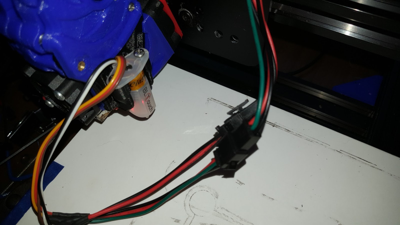
What you do is put your multimeter on 2volt, put the red wire on the potentiometer and the Black one on the GND pin. As my board is oriented in the Photo it is the lowest left pin.
Read on the board to make sure you hit the right one.
If you are unsure or shake a bit then do not do this. You will short something out if one of the probes slip and hit something else. The Red part is going to be stable, as it will go through a hole, but the GND one can easily hit the pins next to it
Both my SilentStepSticks initially measured at 1.1 to 1.2 volt, so I dialed mine Down some. It really very, very small increments they need to turn, so take it slowly
When you get it dialed in, you go back to Method 1 and see if they run smoothly.

Step 5: All done.

Your done. Congratulate yourself on your new, maybe not shiny, but silent 3D printer!
If you find the hissing noise from the motors annoying, you can try adjusting the potentiometers some.

How do I wire up my Black Widow?


Wire up the Widow

I get a lot of questions on how I wire up the Black Widow. I have around 8 different extruding setups that I swap onto my Black Widow so I need and easy way to swap the wiring without cutting anything. So these are my recommendations.

JST Connectors


There are 2 types of JST Connectors for the Black Widows (There is a different set for the Bltouch but I cut them and use the JST Connectors I use here instead) the JST-XHP white connectors that are used to connect to the MKS Control Board and stepper motors and JST SM connectors that are used at the extruder and hoted connectors. Both can be purchased from Amazon (that is where i got mine).
You will also need a crimping tool to crimp the pins to the wires and plug them into the connector.


Pre-Wired Connectors

If you have crazy fingers and arthritis your your fingers (like I do!) then pre-wired would be another option. I purchased the following on Ebay. You will also need a soldering iron and solder along with shrink tubing to protect the soldered connections. This way you do not have to mess with the pins and crimping. I have both options so I can do whatever I need at the time.


Either option will work but these are items you will need to get everything wired up with plug in ease when you need it.

Wednesday, November 9, 2016

Bltouch - Firmware - Working configuration


Actual working BLTouch


After a lot of experimenting I was getting frustrated with the random BLTouch issues. This is not a fault of the Black Widow (unless assembled improperly!) but Marlin firmware itself. The standard right now is the RC7 release of Marlin which is what I was using but I was having very inconsistent results. My bed is pretty level in the first place but I like to have the BLTouch for clearing any variables with my heated bed. The bed will distort a bit with heat up and I like to have super repeat ability like I had with my old Sailfish based printer. So after testing a roll back to RC6 and not being very happy with it (I had going backwards.. I like going forwards) I decided to go out on a limb and start working with the RCBugFix version. This is the version after RC7 but does not yet have an RC status.
Took a few hours to completely tweak the firmware to my printer, remember I downloaded bone stock firmware so there were quite a few things to change and verify before I could start a print.
But after getting the bugs worked out I was able to get prints done with big deviations in the level of the bed without issues. I saw the Z compensating for the out of level while printing. So I'm hoping that this finally gets the nightmare cleared up for now.


You can download the firmware zip file here:
Black Widow RCBugFix Marlin Firmware

BLTouch - How I did it

BLTouch - How I did it

Below I will describe how I setup my Antclabs BLTouch with my Black widow.

Things you will need

Wire - I purchased off of Amazon a 5 wire cable 22 guage


You will also need a set of 3 wire and 2 wire JST connectors that I described in an earlier post.

You will need to download the ANTCLabs official mount from Thingiverse that also includes the update firmware they created and works without modification. This can be downloaded from here:
ANTCLabs BLTouch Mount


You should also download and print the BLtouch gauge. This makes sure your BLTouch is the proper distance from the bed without guessing.

BLTouch Gauge by ProtomakerSprint


Once you have the mount printed out do not update the firmware or remove your existing Z axis end stop until you have installed the mount as well as the BLTouch. The wiring diagram is here:


Make sure your wiring is exactly as shown above. Be sure to translate your wire colors unless you are running wires with the same exact colors. Reversing the servo wires will cause problems. I have not had a problem with switched end stop wires. Just make sure you are using the proper 2 end stop pins for the end stop connection. With you hot end cold bring the nozzle to the bed with a sheet of paper clearance. With the nozzle in position use the gauge you printed earlier to make sure that the BLTouch is the proper distance from the bed (make sure the gauge is on the paper also for proper distance).


Once the connections are in place you can flash the firmware to your board. Slide the existing end stop or remove it from the frame.

Run a G28 or Auto Home to see if everything is moving properly and your extruder homes to the middle of the bed. If the Z axis only moves up instead of down you will have to reverse the direction in the firmware for your Z axis.. I have only seen this randomly but it can happen. If your bltouch is blinking the printer will never Home and the Z will just keep rising. You will have to clear the alarm with M280 P0 S160 this will bring the red led solid and you can try again.

You will want to add the G29 command to your start script in the slicer you are using right after the G28 command

If you would like to make your own mount use the below diagram for the sizing.


Tuesday, November 8, 2016

Options in my firmware

Firmware options I am using

Since the Black Widow is a DIY and the Marlin firmware it runs on is always being improved there are some things I have done to my configuration.

Babystepping

Babystepping allows you to make minor changes when your print starts to change the height of your hotend to the bed. It is much easier to do this than to stop the print and reconfigure your Z end stop. Just add 3 or 4 lines of brim 10mm away from your part and you can adjust your Z height and enjoy your perfect 1st layer every time. Once a print has started you can access the menu by going to Tune - Babystepping Z

File - configuration_adv.h
#define BABYSTEPPING

Screen Timeout

If you have ever worked on the control panel and looked away for a second only to come back to the monitor screen you know the pain. The following will allow the screen to stay were you are longer especially when using your Babystepping:

File - ultracd.h
 #define LCD_TIMEOUT_TO_STATUS 1500000


My Black Widow


Mods I am Using -


  • Tornado Hotend / Extruder
  • Thrust bearings at the bottom of the Z Lead Screws to support the carriage weight
  • Drag Chain alternative X mount
  • Filaprint bed surface
  • RCBugFix Firmware with Bltouch
  • Toothed Idler Pulleys
  • Corner braces instead of hidden braces
  • All bearing removed, cleaned and greased
  • TMC2100 Stepper Drivers